Chapter 6
Power Inside
Electricity enters a data center at a voltage far too high and far too violent for any chip to survive, and getting it down to the roughly one volt a chip actually uses takes a chain of conversions — each one built from equipment that is now astonishingly hard to get.
The Voltage Cascade — From Grid to Chip
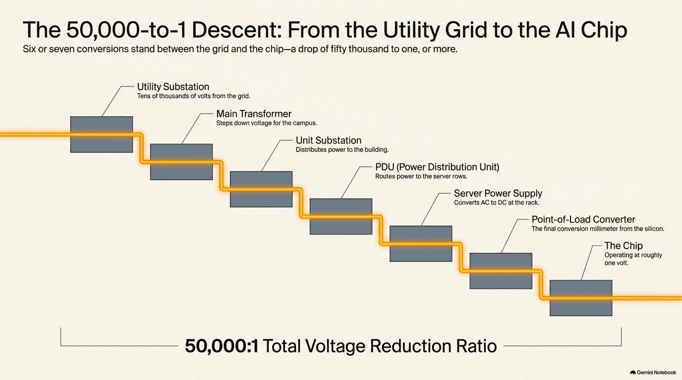
Chapter 5 ended by following a single unit of heat on a journey from a transistor out to the open sky. This chapter follows the opposite journey: electricity, arriving from the outside world at extraordinarily high voltage, being coaxed step by step down to the gentle, low-pressure trickle that a chip can actually use. It's worth being precise about just how large that gap is. Power leaves a distant power plant and travels toward a data center at tens or even hundreds of thousands of volts. A chip — the same chip introduced in Chapter 1, its billions of transistors switching on and off — runs on roughly one volt. That's a difference of somewhere between 50,000 and 500,000 times. Nothing in nature or engineering crosses a gap that large in a single step. It happens instead as a cascade: a series of distinct stages, each one cutting the voltage down by a large factor, each one requiring its own dedicated piece of equipment, and each one converting electricity from one form into another in a way that — as Chapter 5 already established about every energy conversion inside a data center — wastes a small amount of it as heat.
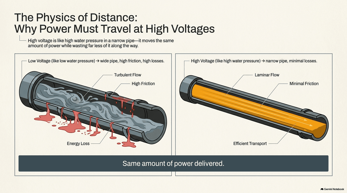
The reason electricity travels at such punishingly high voltage in the first place, rather than simply being generated at a voltage a chip could use directly and sent that way, comes down to a genuinely simple piece of physics that's worth sitting with, because it explains the shape of this entire chapter. Picture two ways of moving the same amount of water through a pipe over a long distance. You could push it through a wide, low-pressure pipe, or you could push the same amount of water through a narrow, high-pressure pipe. The high-pressure, narrow-pipe option loses far less water to friction and leakage along the way, for a simple reason: less material is moving through the walls of the pipe, doing the work of friction, at any given moment — the pressure is doing more of the work of pushing the water forward. Electricity behaves the same way, with voltage playing the role of pressure and current (measured in amps — a measure of how much electrical "stuff" is actually flowing past a point in the wire each second) playing the role of the volume of water moving through the pipe. For a fixed amount of power delivered, raising the voltage lets you lower the current, and lowering the current is what actually matters for the losses, because the energy wasted as heat in a wire — the electrical equivalent of friction — rises with the square of the current, not just in direct proportion to it. Cut the current in half and you don't cut the losses in half; you cut them to a quarter. Cut it to a tenth, and losses fall to a hundredth. That squared relationship is the entire reason the grid moves power at extreme voltage over long transmission lines: it lets the same amount of power travel the same distance while wasting a tiny fraction of what a low-voltage system would waste, using wires that are dramatically thinner, lighter, and cheaper than a low-voltage system would need.
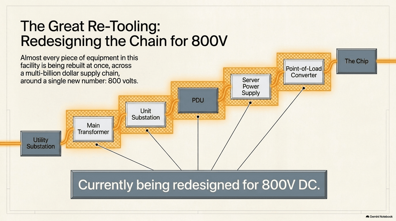
But a low-current, high-voltage wire, ideal for a five-hundred-mile transmission line, is exactly the wrong shape of electricity for almost everything that actually consumes power — building wiring, motors, lighting, and above all, chips, none of which can tolerate anywhere near that voltage without being instantly destroyed. So the cascade runs in reverse of the transmission story: every stage between the power plant and the chip trades voltage back down for current, a little at a time, until the electricity finally arrives in a form gentle enough — high current, extremely low voltage — for a chip's own transistors to switch it on and off billions of times a second without so much as a flicker of concern. The full chain, which the rest of this chapter walks through stage by stage, looks like this: power arrives at the data center's own utility substation at tens or hundreds of thousands of volts; a main transformer steps it down to a level the building's own internal grid can use; a series of smaller unit substations and switchgear step it down further as it's distributed to different sections of the building; a PDU (power distribution unit) delivers it to the row of racks it's responsible for; each server's own power supply unit converts it into the handful of DC voltages the server's internal components need; and finally, a point-of-load converter, sitting right next to or directly on top of the chip itself, performs the very last conversion down to roughly one volt.
Every one of those six or seven stages is a physical device — a transformer, a set of switches, a circuit board full of tiny components — and every one of them, as Chapter 5 already made clear about energy conversion in general, wastes a small percentage of the power passing through it as heat, which then has to be carried away by the cooling systems described in the previous chapter. That's one of the two threads running through this entire chapter: fewer, more efficient conversion stages mean less wasted power and less heat to remove, which is part of why the industry keeps redesigning this chain rather than leaving it alone (a redesign this chapter ends with, in section 6.6). The other thread is scarcity. This cascade is also the reason the electrical room, introduced as one of the major spaces inside a data center in Chapter 4, exists at all and takes up as much floor space as it does — because every one of these conversion stages needs physical equipment, standing in a dedicated room, and as the sections that follow show, almost every piece of that equipment has become one of the hardest things in the entire AI buildout to actually get hold of.
None of this is invisible engineering, tucked away where nobody has to think about it. Every stage of the cascade is instrumented and watched, because a building drawing tens of megawatts cannot afford to discover a problem after it happens. Meters sit at the utility substation, at the main transformer, at each unit substation, and all the way down to the individual rack, continuously reporting how much power is flowing and at what voltage, feeding that information back to the same operations staff who watch over the cooling systems described in Chapter 5. A facility's electrical team can typically see, in real time, exactly how much headroom is left at any point in the cascade — which is part of why the electrical room described in Chapter 4 isn't simply a room full of silent equipment, but one of the more actively monitored spaces in the entire building.
Transformers — Stepping the Voltage Down
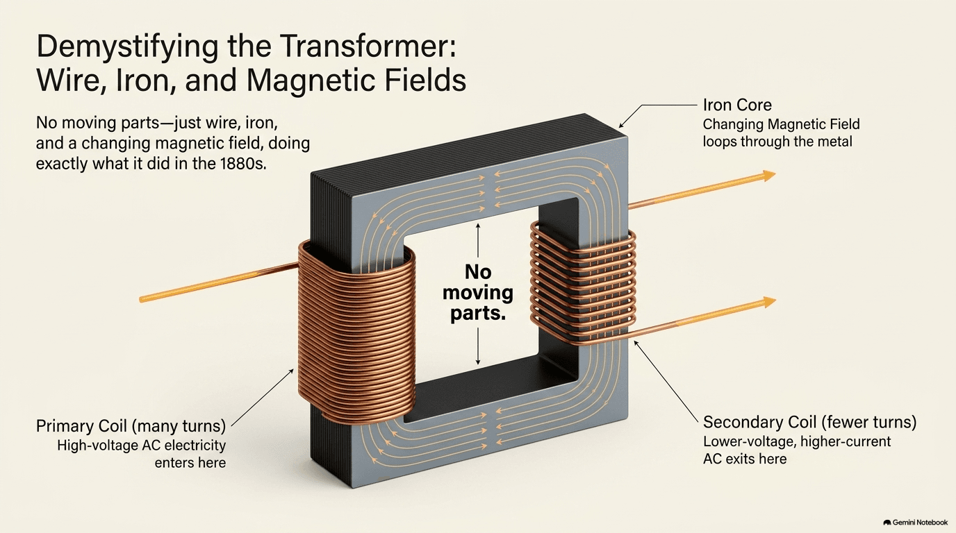
The device that does almost all of the actual work of stepping voltage down — at every stage of the cascade except the very last one — is the transformer, and it's worth understanding what one actually is, because the idea is both far simpler and far older than most of the machinery described elsewhere in this book. A transformer is, at its physical core, two separate coils of wire wrapped around a shared loop of iron. There are no moving parts, no motors, no gears — just wire and iron. When alternating current (electricity that reverses direction many times a second, the kind that comes out of a wall socket and travels across the grid) flows through the first coil, it creates a magnetic field that constantly grows and shrinks inside the iron loop. That constantly changing magnetic field, in turn, induces a new alternating current in the second coil — even though the two coils never touch. This is electromagnetic induction, discovered in the 1830s and turned into a practical, commercially usable transformer in the 1880s, and every transformer built since — from the one on the utility pole outside a house to the largest unit inside a data center's electrical yard — works on exactly that same principle, unchanged in its essentials for well over a century.
The reason this simple arrangement can change voltage at all comes down to how many times each coil is wound around the shared iron core. If the first coil (the one receiving power) has, say, ten times as many turns of wire as the second coil (the one delivering power), the voltage coming out the second coil will be roughly one-tenth of what went in — and, in keeping with the physics described in the previous section, the current coming out will be roughly ten times what went in, since a transformer doesn't create or destroy power, it only trades voltage for current, or current for voltage, in whichever direction the winding ratio points. Wind the coils the other way, with more turns on the output side than the input side, and a transformer can just as easily step voltage up rather than down — which is exactly what happens at the power plant end of the grid, before the transmission story told in section 6.1 even begins. Inside a data center, the job runs almost entirely in the step-down direction: a large utility-class transformer takes power arriving at tens of thousands of volts and steps it down to a level the building's internal electrical system can handle, and then a series of smaller transformers, each one stepping the voltage down further, carry it the rest of the way toward the racks. A single large campus typically needs several of these stages layered on top of each other, not just one — the drop from utility voltage to chip voltage is too large to manage in a single step, echoing the cascade described in section 6.1.
It's worth being clear that "a transformer" is not one single kind of object across this whole cascade — the term covers a wide range of machines, sized very differently depending on where in the chain they sit. The largest utility-class transformers, stepping power down from transmission voltage to the level a building's internal grid can use, are genuinely massive pieces of equipment: multi-story structures filled with oil that both insulates and cools the windings, weighing hundreds of tons, custom-built and tested for the specific voltage and power rating of the site they're headed to. Further down the cascade, the smaller unit substation transformers that step power down a second or third time are far more compact — often dry-type units, cooled by air rather than oil, sized more like a large cabinet than a building — but there are simply more of them, since a large campus needs several unit substations distributed across its footprint to keep the distances busway has to travel (section 6.3) manageable. The bottleneck described below hits hardest at the top of that size range, where the manufacturing process is slowest and the number of factories capable of building at that scale is smallest.
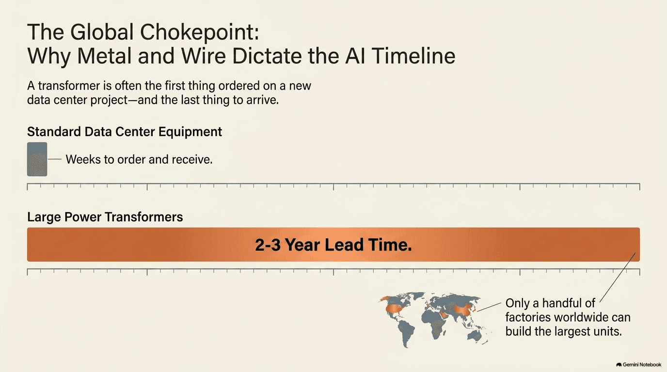
The trouble, and the reason this unglamorous, century-old piece of equipment has become one of the most closely watched bottlenecks in the entire AI buildout, is that the largest power transformers are now genuinely difficult to obtain. Building one of these machines — winding enormous coils of copper wire, stacking precisely engineered iron cores, testing the finished unit at full power before it ever ships — is a slow, specialized manufacturing process, and it happens in only a small number of factories worldwide, most of which were sized for the ordinary pace of utility-grid replacement and expansion, not for the sudden, simultaneous demand created by hundreds of new data center campuses all trying to secure large transformers at once. The result is lead times now commonly measured in years rather than months for the largest units — long enough that securing a transformer order has become, for many projects, one of the very first steps taken, well before construction on the rest of the building even begins, because the transformer is often the single slowest thing standing between "we have a site" and "we have power."
The largest electrical equipment companies in the world sit at the center of this stage of the cascade. Eaton (ETN) makes transformers, switchgear (covered in the next section), and busway, spanning nearly every stage of the voltage cascade described in section 6.1 under one roof. ABB (ABB) is the other truly global electrical giant, making transformers and switchgear at a similar scale and breadth. Valmont (VMI) sits one step further back in the chain, making the steel poles and structures that physically carry power at transmission voltage before it ever reaches a transformer at all — the towers and poles that hold the wires described in section 6.1's pipe analogy up off the ground. And American Superconductor (AMSC), historically known for superconducting-wire technology, has recently expanded directly into manufacturing larger power transformers of its own, a sign of how much new capacity the industry is trying to add to relieve exactly the bottleneck described above.
Switchgear and Distribution
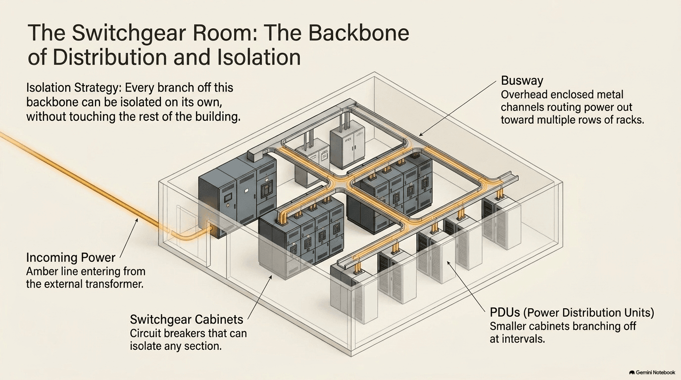
Once the transformer has stepped voltage down, the power still needs to be controlled, protected, and split apart to reach dozens of different destinations inside the building — and that job belongs to switchgear. Switchgear is best understood as a much larger, far more serious relative of the circuit breaker panel in an ordinary house. A home breaker panel lets you cut power to a single room without shutting off the rest of the house, and protects the wiring by tripping automatically if something draws too much current. Data-center switchgear does exactly the same two jobs — isolating one section of the electrical system so it can be serviced or repaired without shutting down everything downstream of it, and automatically interrupting the flow of power if a fault occurs — but scaled up to currents of thousands of amps, housed in steel cabinets the size of shipping containers, engineered to interrupt that much current instantly and safely, without so much as a spark escaping the enclosure. In a building that can never simply be switched off for maintenance, this ability to isolate one piece without touching the rest is not a convenience; it's close to a requirement.
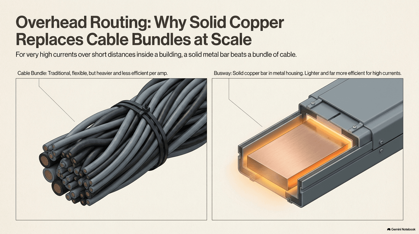
Getting the power that switchgear has controlled and protected physically across a building, in the large quantities a data center needs, is a second, related job usually done by busway (sometimes called busbar): thick, solid bars of copper or aluminum, run in enclosed metal channels along ceilings or walls, in place of the bundled cables an ordinary building might use. For the very large currents flowing through a data center's internal distribution system, solid metal bars turn out to be a more efficient way to carry power than cable — a bar has more metal cross-section available to carry current with less resistance, and can be tapped into at multiple points along its length far more easily than a cable can, letting new circuits be added later without rewiring from scratch. Busway is, in effect, the building's internal power highway, running in long straight runs from the switchgear room out toward the racks it serves.
Switchgear also comes in two broad classes, split by the voltage it's designed to handle, and a data center generally needs both. Medium-voltage switchgear sits close to the main transformer described in section 6.2, handling power still at several thousand volts, before it has been stepped all the way down to the level individual circuits use. Low-voltage switchgear sits further downstream, closer to the final unit substations and PDUs (section 6.5), operating at the few hundred volts a building's internal circuits actually run at. Medium-voltage equipment tends to be the more specialized and more custom of the two — it's engineered for higher voltages and larger fault currents (the surge of current that rushes through during a short circuit or equipment malfunction — a brief but violent spike that the switchgear must be able to safely interrupt), and it's the class most affected by the chokepoint described below.
There's a design principle worth naming here, because it explains why a data center needs so much switchgear in the first place rather than a single central breaker: redundancy. The five-nines uptime standard introduced in Chapter 4 means a facility can't have a single point of failure (one component that, if it breaks, takes down everything downstream of it) anywhere in its power chain, including in the switchgear itself — so critical sections of the electrical system are typically built with a spare path already in place, commonly described as "N+1" (one extra unit beyond the minimum needed) or, for the most critical facilities, "2N" (a fully duplicated, independent second path). That means twice as much switchgear, in some designs, as the electrical load alone would require — a direct, physical cost of the reliability standard the whole building is designed around.
This layer of equipment, unglamorous as it sounds — nobody puts a picture of a switchgear cabinet on a brochure — has become a genuine chokepoint of its own, for a reason distinct from the transformer bottleneck in section 6.2: data-center switchgear is rarely a standard, off-the-shelf product. It's usually engineered and built to the specific electrical layout of a particular building, which means every order effectively starts a custom manufacturing process rather than pulling a finished unit off a shelf, and that custom process can take months from order to delivery even before shipping and installation begin. Powell Industries (POWL) has become the company most associated with exactly this niche — custom-engineered, medium-voltage switchgear, built to order for large industrial and data-center customers — and has been candid that it cannot fulfill every order that comes in the door on the timeline a customer would like, a direct reflection of how far demand for this custom-built equipment has outrun the industry's capacity to build it. Hubbell (HUBB) makes a broad range of utility and electrical distribution products used throughout this stage of the cascade. nVent (NVT) makes the enclosures and electrical connections that house and protect this equipment. And Advanced Energy (AEIS), Littelfuse (LFUS), and Atkore (ATKR) supply, respectively, power-conversion components, the circuit-protection devices (fuses and similar parts) that guard against faults at a smaller scale than switchgear itself, and the conduit — the protective tubing that electrical wiring is run through inside a building's walls and ceilings.
UPS and Backup Power — When the Grid Fails
Chapter 4 introduced the "five nines" standard that hyperscale data centers are built around — 99.999 percent uptime, meaning less than about five minutes of unplanned downtime across an entire year. That standard has a direct and demanding consequence for the power chain described in this chapter: the electricity flowing down through the cascade in section 6.1 cannot simply stop, even for a fraction of a second, when something goes wrong out on the public grid. A brief voltage sag, a lightning strike on a distant transmission line, a full-scale outage — any of these, left unaddressed, would instantly cut power to every server in the building, and computing equipment does not tolerate even a momentary interruption gracefully. The industry's answer is to layer two entirely different kinds of backup power on top of the grid connection, each one covering for a gap the other can't.
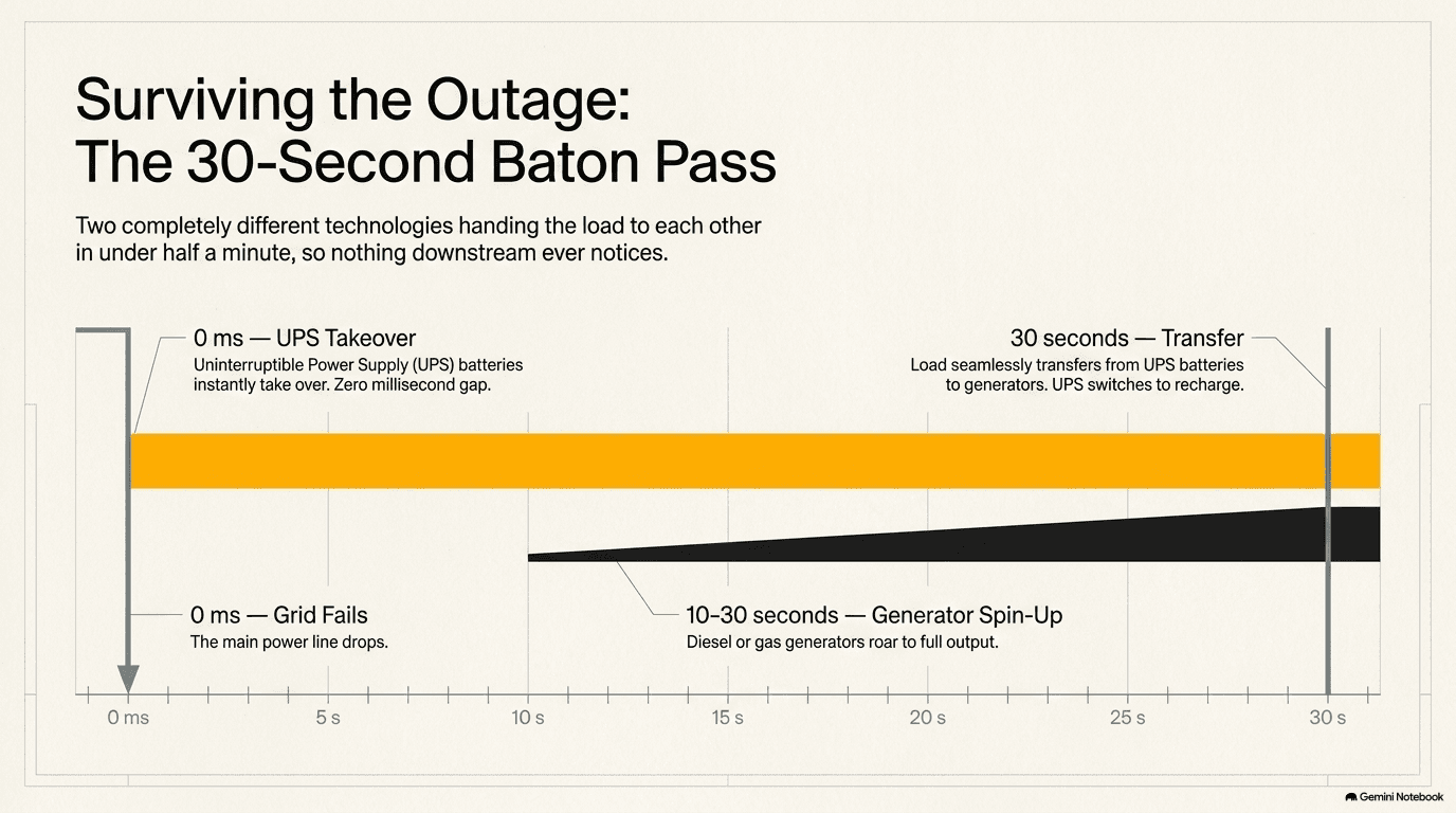
The first layer is the UPS, or Uninterruptible Power Supply — in its essence, a very large, very fast bank of batteries paired with power-conversion electronics sophisticated enough to detect a grid failure and switch the building's load onto battery power within a fraction of a second, fast enough that the servers downstream never notice the grid disappeared at all. A UPS isn't designed to run the building for hours; its job is to bridge a gap measured in seconds, buying time for the second layer of backup to wake up and take over. That second layer is the generator — a diesel or natural-gas engine, closely related in principle to the larger on-site power generation described in the next chapter, but built and sized specifically as dedicated backup rather than as a primary source of power. Generators cannot start and reach full, stable output instantly the way a UPS can switch to batteries instantly; a diesel engine has to physically start turning, come up to speed, and stabilize its own output, a process that typically takes something on the order of ten to thirty seconds. That gap — the time between the grid failing and the generators reaching full, reliable output — is precisely the gap the UPS exists to cover, and the handoff between the two is a carefully engineered sequence, not a coincidence: the moment the grid fails, the UPS instantly begins supplying the entire building's load from its batteries; within seconds, the generators start and begin ramping up; once the generators reach stable, full output, the building's load is transferred onto them; and the UPS, no longer needed to carry the load, switches back to simply recharging its own batteries, ready to bridge the next gap whenever it happens. If the grid comes back before the generators are even needed, the whole sequence reverses just as smoothly, with the building's load handed back to the grid and the generators shutting back down.
Data-center backup generators are most commonly diesel-fueled, for a practical reason: diesel can be stored on-site in large tanks for long periods without much special handling, giving a facility a fuel supply it fully controls rather than depending on a live pipeline connection at the exact moment the grid has already failed. Some facilities instead use natural-gas generators, or engines that can run on either fuel, trading the self-contained certainty of an on-site diesel supply for the convenience of not needing large fuel tanks and periodic deliveries at all — a tradeoff between reliability and logistics that different operators weigh differently depending on their site. Whichever fuel is chosen, backup generators aren't simply installed and left alone until the day they're needed: because a piece of equipment that sits idle for months at a time is exactly the kind of equipment most likely to fail silently, data centers routinely run scheduled test cycles — starting the generators, running them under load for a period, and confirming the entire UPS-to-generator handoff sequence described above actually works — so that the first real test of the backup system is never the first time it's genuinely needed.
Backup generators have become, alongside the transformer described in section 6.2, one of the more visible equipment bottlenecks in the whole AI buildout, for a similar underlying reason: demand for dedicated, large-scale backup generation has climbed sharply and simultaneously across a huge number of new data-center projects, and lead times for large generator sets — engines, alternators, the control systems that manage them — have stretched out substantially as a result, in some cases roughly doubling compared to a few years earlier. Generac (GNRC) makes large generators aimed specifically at data-center backup power. Cummins (CMI) makes diesel and natural-gas generators and the broader power systems built around them. Caterpillar (CAT), better known for construction equipment, is also a major maker of both generators and backup power systems for large facilities. On the battery side of the UPS itself, EnerSys (ENS) makes the batteries used inside data-center UPS systems. And a related but distinct category of company has grown up around a slightly different job — not bridging a ten-second gap during an outage, but helping smooth out the electricity supply more broadly, absorbing and releasing power to firm up a facility's overall power picture: grid-scale battery storage makers including Tesla (TSLA), with its Megapack product line, Fluence (FLNC), and Eos Energy (EOSE) all supply this kind of large-scale storage, which increasingly sits alongside — though it is not a direct substitute for — the fast-acting UPS-and-generator pairing described above.
Down to the Rack — PDUs and Point-of-Load
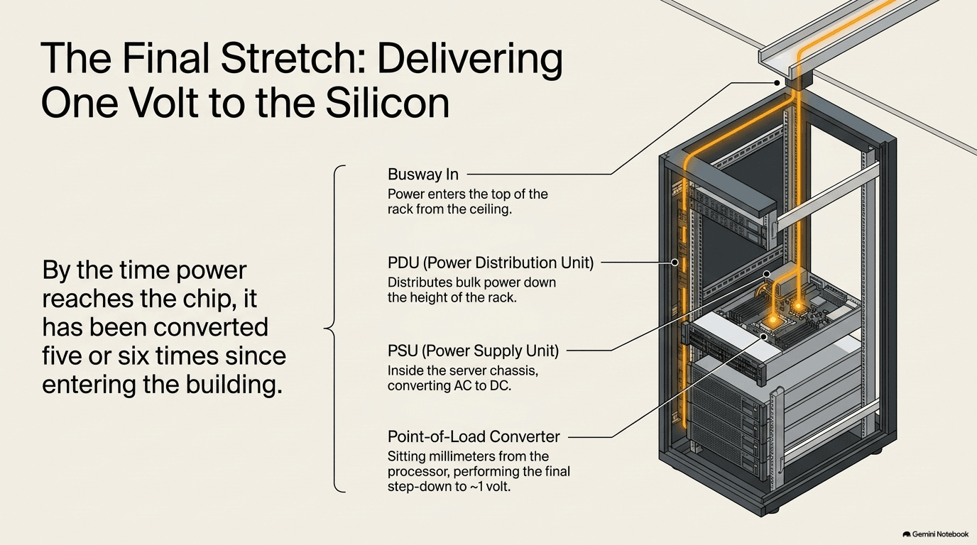
The last three stages of the voltage cascade sketched out in section 6.1 all happen inside, or right next to, the rack itself, and each one operates over a progressively smaller distance and a progressively smaller voltage step than the ones before it. The first of the three is the PDU — the power distribution unit — which is the point where power arriving from the building's busway (section 6.3) is finally handed off to an individual rack. A rack PDU is, in effect, an industrial-grade, heavily instrumented power strip: it distributes power out to every server plugged into that rack, and it also monitors how much power each connection is drawing in real time, feeding that information back to the building's overall power-management systems so operators can see exactly how close any given rack is to its power limit — a genuinely important thing to know in a building where racks can draw tens of thousands of watts each, as Chapter 5 described.
Inside each individual server, a power supply unit, or PSU, takes the AC power the PDU delivered and converts it into the handful of steady DC voltages the server's internal components actually need — a somewhat higher voltage for some components, a lower one for others — performing, at server scale, essentially the same kind of conversion job the much larger transformers in section 6.2 perform at building scale. But even that isn't the final step. The GPUs and CPUs at the very heart of the server, introduced in Chapter 1 and assembled onto boards in Chapter 2, need a voltage so low — around one volt — and a current so high in absolute terms that the power simply cannot travel any real distance across a circuit board without unacceptable losses. So the very last conversion happens as close to the chip as physically possible: a point-of-load converter, a small module sitting directly beside or, in the newest designs, mounted directly on top of the chip package itself, takes the server's internal DC voltage and steps it down that final stretch to the roughly one volt the chip actually runs on. This is the arrangement Chapter 2 described, in the context of the board itself, as "vertical power delivery" — pushing that last, most sensitive conversion stage as physically close to the chip as engineering allows, because every extra millimeter of circuit board a high-current, low-voltage signal has to travel is a millimeter of additional loss.
A modern rack PDU takes the monitoring idea introduced in section 6.1 to its finest level of detail: rather than reporting one combined figure for the whole rack, it can typically report power draw circuit by circuit, and often server by server, giving operators a live, granular picture of exactly which piece of equipment is drawing how much power at any given moment — the same kind of visibility, at much finer resolution, that Chapter 5 described for tracking heat and airflow. That granularity matters for a very practical reason: it lets a facility load racks up close to their power limit with confidence, rather than leaving a wide, wasteful safety margin simply because nobody could see exactly how much any individual server was drawing.
Point-of-load conversion, for its part, has its own efficiency story worth noting, because it connects directly back to Chapter 5's argument about heat. A conversion stage that wastes even a few percent of the power passing through it, multiplied across thousands of chips in a data center, adds up to a genuinely large amount of extra heat that then has to be removed by the cooling systems described in the previous chapter — so point-of-load modules are engineered to be as efficient as the underlying electronics allow, typically converting well above ninety percent of the power that enters them into usable power at the chip, rather than heat. Every fraction of a percentage point of improvement here is, in effect, heat that Chapter 5's cooling chain never has to deal with in the first place.
Vicor (VICR) is the company most closely associated with these point-of-load modules, supplying the compact, high-density power conversion that performs this final, closest-to-the-chip step of the entire cascade traced through this chapter. Vertiv (VRT) — already introduced in Chapters 4 and 5 for its work on building infrastructure and liquid cooling — also supplies the rack-level PDUs and busway that carry power the last stretch from the building's distribution system into the rack itself, making it, like Eaton in section 6.2, a company that touches multiple separate stages of this same cascade.
The 800-Volt Shift
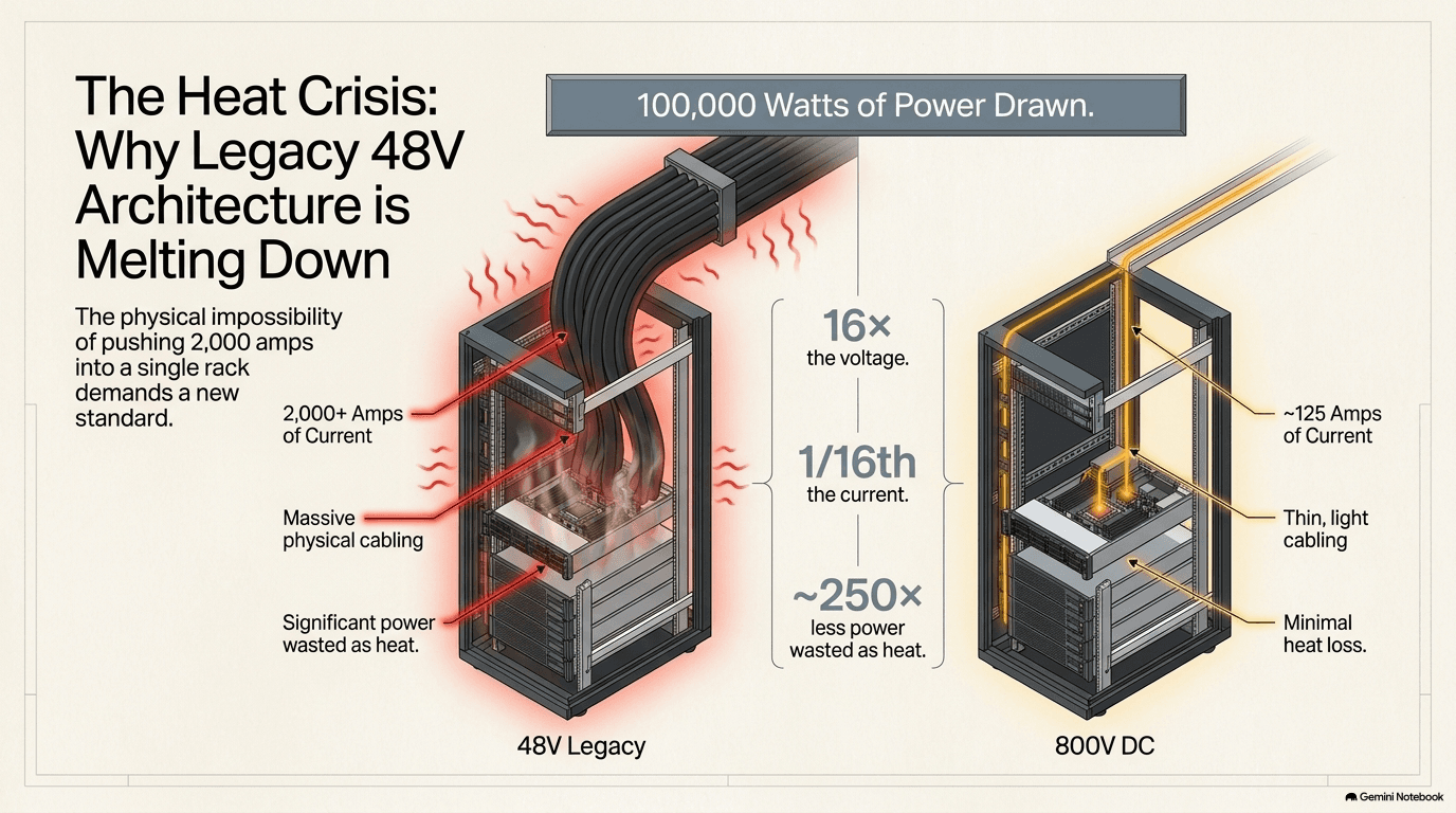
Every stage of the cascade described in this chapter — the transformer, the switchgear, the UPS, the PDU, the point-of-load converter — has, until quite recently, been built around a fairly stable set of voltages that changed only slowly over the decades. That stability is now breaking, all at once, across the entire chain, and the reason traces directly back to the heat and density story told in Chapter 5. As individual racks have climbed past 100,000 watts of draw, the traditional lower-voltage architecture used to feed them — power distributed inside the rack at roughly 48 or 54 volts — has run into the exact same physics described at the start of this chapter in the water-pipe analogy, but now playing out over a distance of feet rather than hundreds of miles.
The arithmetic is worth working through directly, because it explains why this is treated as a genuine engineering shift rather than a minor product update. Delivering 100,000 watts of power at 48 volts requires a current of a little over 2,000 amps — an amount of current that demands extremely thick, heavy copper conductors just to carry it without melting, and that still wastes a meaningful fraction of the power as heat along the way, precisely because, as section 6.1 explained, resistive losses rise with the square of the current. Delivering that same 100,000 watts at 800 volts, by contrast, requires roughly one-sixteenth of that current — around 125 amps. Because losses scale with the square of current, cutting the current to roughly a sixteenth of its previous value doesn't cut losses by a factor of sixteen; it cuts them by roughly the square of sixteen, close to 250 to 300 times less loss for the same conductor, or, viewed the other way, it lets the conductor itself shrink dramatically — thinner, lighter cable and busway carrying the identical amount of power. That is the entire logic behind the industry's shift to 800-volt direct current as the new standard for power inside the rack: not a marketing refresh, but a direct response to the same squared relationship between current and heat that governs the long-distance transmission lines described at the top of this chapter, now applied at the scale of a single rack.
This is genuinely new engineering, not simply a bigger version of equipment the industry already knew how to build, and part of what makes it possible is a shift happening at the level of the materials the power electronics themselves are built from. For decades, the semiconductor switches inside power converters — the components that actually do the work of chopping and reshaping current at every conversion stage in this chapter — were built almost exclusively from ordinary silicon, the same base material introduced in Chapter 1. Two newer materials, gallium nitride (GaN) and silicon carbide (SiC), can switch current on and off far faster and tolerate far higher voltages and temperatures than traditional silicon power switches can, while wasting less energy doing it. That combination — faster switching, higher voltage tolerance, lower losses — is close to a checklist of exactly what's needed to build compact, efficient power electronics rated for 800 volts rather than 48, which is why GaN and SiC components are treated as a key enabling technology for this entire shift, sitting quietly inside the point-of-load converters, solid-state transformers, and other power-electronics products described throughout this section, even though they rarely appear by name on any equipment's exterior.
Direct current itself also behaves differently from the alternating current used almost everywhere else in this chapter's cascade, and redesigning a rack's internal power architecture around 800-volt DC touches nearly every piece of equipment described in the sections above: the point-of-load converters in section 6.5 have to be redesigned to step down from a much higher starting voltage in one larger jump instead of several smaller ones; the busway and PDUs in sections 6.3 and 6.5 have to be re-rated for a different voltage and current profile entirely; and further back up the chain, some of the transformation work traditionally done in stages, using conventional transformers, is being pushed toward newer devices called solid-state transformers — power-electronics-based converters, built from semiconductor switches rather than only wire and iron, that can be more compact and more flexible about the exact voltages and currents they handle than a traditional transformer of the kind described in section 6.2. This shift has, by most accounts, been led by NVIDIA (NVDA), whose data-center chip designs — introduced in Chapter 1 — are increasingly built around the assumption that rack-level power will arrive as 800-volt DC rather than the lower-voltage AC architecture the industry has used for decades, effectively setting a new specification that the rest of the power-equipment industry is now racing to build for.
Eaton is developing solid-state transformers aimed specifically at this new architecture, extending the same transformer business described in section 6.2 into this newer, power-electronics-based form. ABB is co-developing an 800-volt DC power architecture directly with NVIDIA, putting one of the two global electrical giants introduced in section 6.2 at the center of defining what the new standard actually looks like in practice. And the shift connects forward into the next chapter in a way worth flagging here: Bloom Energy's (BE) fuel cells, covered in Chapter 7 as a form of on-site power generation, produce direct-current electricity at 800 volts as a natural output of the chemical process inside them, rather than needing to be converted into that form afterward — meaning that as data centers increasingly generate some of their own power on-site, some of that power can, in principle, skip several of the conversion stages traced through this entire chapter and arrive close to the voltage the rack needs almost directly. That's a preview of the next chapter's subject: this one has followed power on its journey down from the grid to the chip; the next follows it back further still, to the question of where that power comes from in the first place, and what happens when a data center decides the public grid isn't enough and builds its own source of it instead.
Next: Chapter 7 — On-Site Utilities (when the public grid isn't enough, and a data center builds its own source of power)
Companies in this part of the buildout: Power Systems